BLOG CLOSED
Please visit my new blog www.emrlab.wordpress.com
Thanks for visiting!
Thursday, July 11, 2013
Thursday, October 11, 2012
Installing BIND9 on FreeBSD 9

mkdir /usr/tmp
cd /usr/tmp
pkg_add -v -r perl
wget ftp://ftp.isc.org/isc/bind9/9.9.1-P3/bind-9.9.1-P3.tar.gz
gzip bind-9.9.1-P3.tar.gz
tar -xfv bind-9.9.1-P3.tar
cd bind-9.9.1-P3.tar.gz
./configure
make
make install
pkg_add -r nano
ln -s /usr/local/bin/nano /usr/bin/nano
/var/named/etc/namedb/
nano named.conf
TO DO: Post named.conf example and zone files for my simple DNS server
TO DO: Add IPV6 AAAA Records
TO DO: Look into DNSSEC
GRE between Vyatta Core & pfSense

Vyatta:
vyatta@vyatta1-site1:~$ show configuration
interfaces {
ethernet eth0 {
address 192.168.1.1/24
duplex auto
hw-id 00:0c:29:00:a3:d7
smp_affinity auto
speed auto
}
ethernet eth1 {
address dhcp
duplex auto
hw-id 00:0c:29:00:a3:e1
smp_affinity auto
speed auto
}
loopback lo {
}
tunnel tun0 {
address 192.168.10.1/30
description "GRE TUNNEL TO SITE2"
encapsulation gre
local-ip 10.1.1.2
multicast enable
remote-ip 10.2.2.3
ttl 255
}
}
protocols {
ospf {
log-adjacency-changes {
}
parameters {
abr-type cisco
rfc1583-compatibility
router-id 2.2.2.2
}
}
static {
route 0.0.0.0/0 {
next-hop 10.1.1.1 {
}
}
}
}
service {
nat {
rule 1 {
outbound-interface eth1
source {
address 192.168.1.0/24
}
type masquerade
}
}
pfSense:


TO DO:
Secure tunnels with IPSEC + Firewall rules on both sides
Enable dynamic routing between sites.
Thursday, September 20, 2012
GRE Tunnels with NAT Overload CISCO

************************************************************************
SITE1#show run
!
interface Tunnel0
ip address 172.16.1.1 255.255.255.0
ip nat inside
tunnel source 209.165.0.2
tunnel destination 209.165.1.2
!
interface FastEthernet0/0
description ISP LINK
ip address 209.165.0.2 255.255.255.224
ip nat outside
duplex auto
speed auto
!
interface FastEthernet0/1
ip address 192.168.1.1 255.255.255.0
ip nat inside
duplex auto
speed auto
!
router rip
version 2
redistribute static
passive-interface FastEthernet0/0
network 172.16.0.0
network 192.168.1.0
no auto-summary
!
ip nat inside source list ALLOWED_NAT_ADDRESSES interface FastEthernet0/0 overload
ip classless
ip route 172.16.1.0 255.255.255.0 Tunnel0
ip route 209.165.1.0 255.255.255.224 209.165.0.1
no ip http server
ip pim bidir-enable
!
!
ip access-list standard ALLOWED_NAT_ADDRESSES
permit 192.168.1.0 0.0.0.255
permit 172.16.1.0 0.0.0.255
!
************************************************************************
SITE2#show run
!
interface Tunnel0
ip address 172.16.1.2 255.255.255.0
ip nat inside
tunnel source 209.165.1.2
tunnel destination 209.165.0.2
!
interface FastEthernet0/0
ip address 209.165.1.2 255.255.255.224
ip nat outside
duplex auto
speed auto
!
interface FastEthernet0/1
ip address 192.168.2.1 255.255.255.0
ip nat inside
duplex auto
speed auto
!
router rip
version 2
redistribute static
passive-interface FastEthernet0/0
network 172.16.0.0
network 192.168.2.0
no auto-summary
!
ip nat inside source list ALLOWED_NAT_ADDRESSES interface FastEthernet0/0 overload
ip classless
ip route 172.16.1.0 255.255.255.0 Tunnel0
ip route 209.165.0.0 255.255.255.224 209.165.1.1
no ip http server
ip pim bidir-enable
!
!
ip access-list standard ALLOWED_NAT_ADDRESSES
permit 192.168.2.0 0.0.0.255
permit 172.16.1.0 0.0.0.255
!
************************************************************************
SITE1#ping 172.16.1.2
Type escape sequence to abort.
Sending 5, 100-byte ICMP Echos to 172.16.1.2, timeout is 2 seconds:
!!!!!
Success rate is 100 percent (5/5), round-trip min/avg/max = 32/53/84 ms
SITE1#show ip route
Gateway of last resort is not set
1.0.0.0/32 is subnetted, 1 subnets
R 1.1.1.1 [120/1] via 192.168.1.2, 00:00:13, FastEthernet0/1
172.16.0.0/24 is subnetted, 1 subnets
C 172.16.1.0 is directly connected, Tunnel0
209.165.0.0/27 is subnetted, 1 subnets
C 209.165.0.0 is directly connected, FastEthernet0/0
209.165.1.0/27 is subnetted, 1 subnets
S 209.165.1.0 [1/0] via 209.165.0.1
C 192.168.1.0/24 is directly connected, FastEthernet0/1
R 192.168.2.0/24 [120/1] via 172.16.1.2, 00:00:06, Tunnel0
SITE1#
************************************************************************
SITE2#ping 172.16.1.1
Type escape sequence to abort.
Sending 5, 100-byte ICMP Echos to 172.16.1.1, timeout is 2 seconds:
!!!!!
Success rate is 100 percent (5/5), round-trip min/avg/max = 16/52/88 ms
SITE2#show ip route
Gateway of last resort is not set
1.0.0.0/32 is subnetted, 1 subnets
R 1.1.1.1 [120/2] via 172.16.1.1, 00:00:09, Tunnel0
172.16.0.0/24 is subnetted, 1 subnets
C 172.16.1.0 is directly connected, Tunnel0
209.165.0.0/27 is subnetted, 1 subnets
S 209.165.0.0 [1/0] via 209.165.1.1
209.165.1.0/27 is subnetted, 1 subnets
C 209.165.1.0 is directly connected, FastEthernet0/0
R 192.168.1.0/24 [120/1] via 172.16.1.1, 00:00:09, Tunnel0
C 192.168.2.0/24 is directly connected, FastEthernet0/1
SITE2#
************************************************************************
Wednesday, September 19, 2012
All Things Switching
All Things
Switching
- Hubs – Depreciated. Hubs create one big collision domain as well as one huge broadcast domain.
- Bridge – A device that is used to segment collision domains. Place bridges between multiple hubs or switches. They don’t do anything to decrease the broadcast domain size.
- Switches – Switches place each host in its own collision domain. Switches do not break up broadcast domains by default. VLAN’s assist with that.
CSMA/CD – Carrier
Sense Multiple Access with Collision Detection
A host that wants to send data will first “listen to the
wire,” meaning checking that shared media to see if it is in use.
If the media is in use, the host will wait until the line is
clear to send data.
If data is sent at the same time, a collision occurs; the
voltage on the wire will change to indicate this.
If this happens, hosts send a “jam signal” which indicates
to other hosts that the collision needs to be dealt with before others can
attempts to send. The back off timer initiates and once that expires, the
“listen to the wire” process begins again.
Switching Theory:
Switches do three things with the frames they receive.
Flooding – Performed
when the switch has no entry for the frame’s destination MAC address. When a
frame is flooded it is sent out of every port except the frame it came in on.
Forwarding –
Performed when the switch does have an entry for the frame’s destination MAC address.
Forwarding simply means it is sent out ONE port of the switch.
Filtering –
Performed when the switch has an entry for both the source and destination MAC
address, and the MAC table indicates that both addresses are found off of the
same port.
Switches use the source MAC address to build their MAC
address database.
Unknown unicast frame is ALWAYS flooded.
Switches NEVER send a frame back out the same port it came
in on.
MAC table Names: CAM Table, Bridging Table, Switching Table,
MAC Table
Frame Processing
Store-and-forward –
Entire frame is stored by the switch and forwarded to the host. The switch
stores the frame before it looks at the FCS. This allows the best method of
error detection.
Cut-through – Reads
the MAC address on the incoming frame, and then immediately forward the frame
even while some of it is still being received. FCS is not being considered
here, although this is the fastest of the three processes.
Fragment-free – If
a frame is corrupted it is going to be in the first 64 bytes of the frame, so
the switch only checks these first 64-bytes.
Three Layer Switching
Model:
- Core
- Distribution
- Access
Campus Network: is a computer network made up of an
interconnection of local area networks (LANs) within a limited geographical
area.

Redundancy – A backup or multiple paths around the network.
Switching loops are introduced with redundancy however, and
this is where the spanning tree protocol comes into play.

Spanning Tree
Protocol
STP, defined by IEEE
802.1d, prevents switching loops from occurring by placing ports along the
most desirable path into forwarding mode,
and placing ports along less-desirable paths into blocking mode.
Root bridge election for each VLAN – Per-VLAN Spanning Tree
– so prevalent it is most commonly referred to as STP.
Root Bridge: A
bridge which continuously transmits network topology information to other
bridges, using the spanning tree protocol, in order to notify all other bridges
on the network when topology changes are required.
This means that a network is able to reconfigure itself
whenever a network link (e.g. another bridge) fails, so an alternative path can
be found. The presence of a root bridge also prevents loops from forming in the
network.
BPDU – Bridge Protocol Data Unit (Originating or Forwarding)
Sent every two seconds. Contains the Priority and the MAC address.
BID – Root Bridge ID: Combination of the bridge’s priority
and MAC address. The bridge with the lowest BID will be the root bridge. The
default priority is 32768 for all switches; therefore, since the lowest BID
wins, the switch with the lowest MAC address will become the root bridge unless
the priority is changed. Priority is some value between 0-61440. (Increments of
4096)
Port States:
- Blocking – Frames are not forwarded, but BPDU’s are accepted.
- Listening – Frames are not forwarded, and the MAC address table is not yet being built.
- Learning – Frames are not forwarded. MAC addresses are being learned and the MAC address table is being built.
- Forwarding – Frames are forwarded. MAC addresses are still learned.
Root switch is going
to have all of its ports in forwarding mode!
Port Types:
- Root Port: Used to reach the root bridge.
- Designated port: Forwarding port, one per link.
- Blocking/Non Designated Port: Where the tree fell. Not used.
Manipulating Spanning Tree:
Configure SW3 to be a root bridge:

SW1(config)#spanning-tree vlan 1 priority 100

Manipulating which links are blocked:
(As you can see. SW3 has put port fa1/1 into blocking mode to prevent a loop)
SW3(config)#int fa1/0
SW3(config-if)#spanning-tree cost 300
Changing the cost of the fa1/0 link to more than the default will force that link to be put into blocking mode:

Here we see a list of various Costs associated with link types based on the bandwidth:
Bandwidth Cost
===================
4 Mbit/s 250
10 Mbit/s 100
16 Mbit/s 62
45 Mbit/s 39
100 Mbit/s 19
155 Mbit/s 14
200 Mbit/s 12
622 Mbit/s 6
1 Gbit/s 4
2 Gbit/s 3
10 Gbit/s 2
20 Gbit/s 1
===================
===================
4 Mbit/s 250
10 Mbit/s 100
16 Mbit/s 62
45 Mbit/s 39
100 Mbit/s 19
155 Mbit/s 14
200 Mbit/s 12
622 Mbit/s 6
1 Gbit/s 4
2 Gbit/s 3
10 Gbit/s 2
20 Gbit/s 1
===================
Port Fast:
Allows you to skip the listen and learning phases of STP,
but should ONLY be used on a port directly connected to a host. Port Fast
allows communication to occur much quicker.

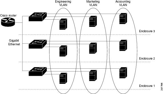
VLANS
Another important topic. Used to break up broadcast domains. Remember when a switch receives a broadcast it forwards it out EVERY port of its switch. Broadcast messages are OK, but when too many of them occur, the switch takes a hit on the CPU & memory. Also, continual broadcasts can result in a broadcast storm, which can also disable the switch.
VLANs are usually logically segmented by the department of an organization. They are also segmented by subnets.
VLANs are not technically a security feature, but they have grown to be.
VLAN Trunks
VLAN trunks are essentially one link that carries all of your VLAN's over it.

There are two protocols that are used to do this, one is Cisco's proprietary ISL, which encapsulates the entire frame before it is sent over the link.
The other is IEEE 802.1q which is the industry standard trunking protocol. You must use 802.1q (or just dot1q) if you are using vendor switches other than Cisco. Dot1q does not encapsulate the entire frame, instead a 4-byte header is added to the ethernet header, indicating the VLAN to which the frame is intended.

Native VLAN = Default VLAN
Where is it used? To understand the NATIVE VLAN, someone mentioned to me the Cisco IP phone. Cisco IP phones that have 2 ethernet ports are kind of like a small 2-port switch. You connect your PC to your phone, and your phone to the switchport. On the switchport you configure the voice VLAN, and then set the NATIVE VLAN to your "data" or "host" VLAN. Untagged frames that enter that switchport (those from the PC) are sent to the NATIVE VLAN, and those tagged from the phone are sent down the voice VLAN.
Creating a VLAN and Configuring a Trunk

View the created VLANs below:

Configuring a trunkport on a Cisco switch:

!
Subscribe to:
Posts (Atom)